| Thread Links | Date Links | ||||
|---|---|---|---|---|---|
| Thread Prev | Thread Next | Thread Index | Date Prev | Date Next | Date Index |
|
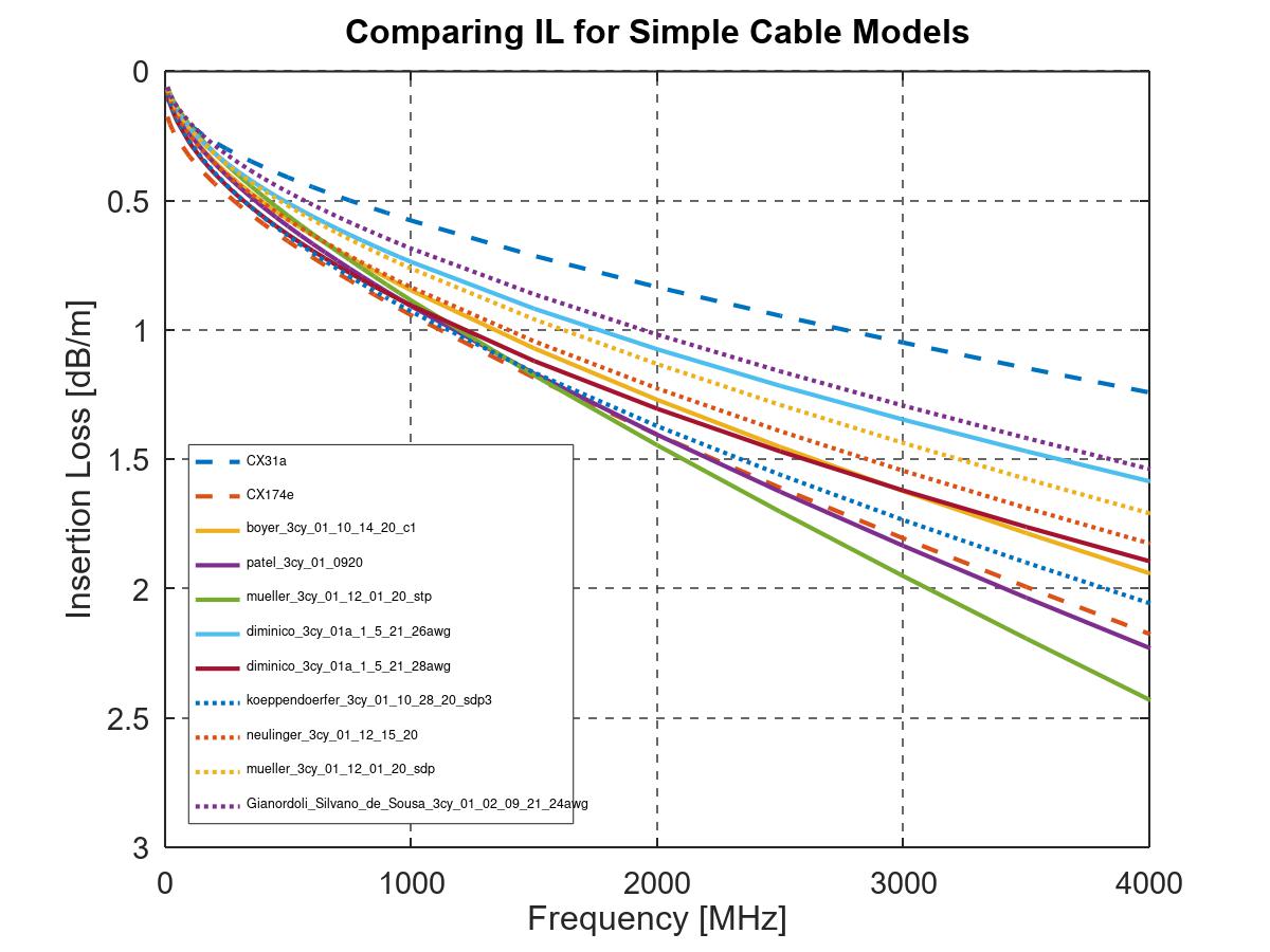
All, One of the factors that has been brought up in the discussion on IL-limits is that Coax and SDP cables have different insertion loss. While this is definitely true, it is also true that there is
considerable variation in insertion loss within both categories. The enclosed plot shows simplified insertion loss models for number of cables that where discussed in the development of 802.3cy, as well as the coax cable limits (CX31a and CX174e) discussed
in our Annapolis meeting. The plot shows that the insertion loss for most of the STP/SDP cables falls between the limits for CX31 and CX174. While the cables introduced for 802.3cy may not all be representative for the camera
application, this plot demonstrates that there is not a fundamental difference between Coax and SDP cable insertion loss. Please note that the curves are simplified, and they do not correctly reflect frequency dependent variations like suck-out in the cables. In fact, Jonathan suggested in his email below that “probably
STP cables should also have “speed grades” as the IL “suck-out” will determine the maximum operating frequencies of the differential pair”, which I think that the Task Force should consider. This could be done by limiting the frequency range of the IL-limit,
depending on the data rate. Some background on the simplified cable models I used is that the model assumes the commonly used insertion loss function IL(f) = a + b*f + c*sqrt(f) + d./sqrt(f) where f is the frequency in MHz and the coefficients are given in the table at the bottom of this email (note that I used d equal zero for all the models in the plot). The coefficients were obtained
by curve fitting to the plots from the 802.3cy presentations (in the fitting for the 802.3cy cable plots I only used b and c for the fitting). The parameters for CX31a and CX174e were obtained by using curve fitting to available plots (note that I am not using
official parameters from 19642-11). Ragnar
From: Ragnar Jonsson
Hi Kirsten, Thank you for pointing out the previous work on ASA and A-PHY. I think that it would be appropriate for those who want to adopt either of these limits to bring in presentation with explicit IL-limit
proposal and with explanation of why these are applicable for 802.3dm. By the way, there are number of other existing IL-Limits that have considerable work and expertise behind them, including the ones defined for 802.3ch and 802.3cy. While I am not advocating for adopting
either of these limits for 802.3dm, I think that both of these could be viable candidates, if they meet the requirements for what we are trying to do in 802.3dm. Ragnar From: Kirsten Matheus <Kirsten.Matheus@xxxxxx>
Prioritize security for external emails: Confirm sender and content safety before clicking links or opening attachments
Hello Ragnar, thank you for pointing out the previous work done on this. IEEE 2977-2021 does define two different IL limit lines for STP and Coax cabling. I highly recommend to leverage from previous work done on this in IEEE 2977, in ASA (specification available in the
private area of the 802.3) and ISO, instead of reinventing the wheel. A lot of work and expertise has already gone into this.
Kind regards, Kirsten Von: Ragnar Jonsson <rjonsson@xxxxxxxxxxx>
All, I have been doing some more digging into what we should expect in terms of relative noise levels between Coax and Shield Differential Pair (SDP). One data point is that in IEEE 2977-2021 (A-PHY)
defines the same coupling attenuation for both Coax and SDP (see Section 6.6.2.4 of 2977-2021). This would suggest that the noise levels are similar for Coax and SDP at the MDI. I think that the Task Force would benefit from more information about the relative
noise levels for Coax vs SDP, in particular related to Electro Magnetic Interference (EMI). Ragnar From: Ragnar Jonsson <rjonsson@xxxxxxxxxxx>
All, I think that the points raised by Jonathan, Bert and George below are all good. Regarding the aging, we need feedback from cable experts to understand if aging is included in the ISO 19642-11 IL limits. If they are not, then we can probably scale the limits to find the right
IL limits for 802.3dm. Regarding one or two IL limits, I sounds like George is thinking along the same lines as I am, that from a technical point of view this mainly depends on the SNR at the receiver. To better understand
any such differences in the SNR, it would be good to get better understanding of the noise coupling into the different cable types. Can anyone share information about what coupling functions we should expect from external electric field into the signals at
the MDI? Ragnar From: George Zimmerman <george@xxxxxxxxxxxxxxxxxxxx>
Prioritize security for external emails: Confirm sender and content safety before clicking links or opening attachments
Bert and Silvano – thank you for your expertise. (and thank you Ragnar for raising the question). I think Silvano’s assumption about whether aging is included in the ISO specifications. Who should we ask for a definitive answer (or is there sufficient expertise
and agreement among the experts here within our group?). From here on out, it gets more complicated. From the standpoint of whether we should have one or two link segment IL specifications, I think that ends up being determined by whether there is an impact on the
PHY. Our goal is to write one or more link segment specifications that all phys must be able to operate over. The question becomes where do the PHY types become different. Yes, different media will operate differently, but our goal isn’t to model the IL
of the medium, but rather to make sure the medium can meet the spec, not necessarily fit it tightly, so that the PHY designs can run over it. I believe most in the group are considering a single PCS/PMA (PHY chip) as the target, not specialized chips for
each medium. Now, note I said PCS/PMA or “PHY Chip”. The PHY type means more than the transceiver chip, but the interface circuitry from the MII (interface to the RS) to the MDI
interface to the media). Certainly an MDI connecting to a balanced medium (with differential signals) would be different from an MDI connecting to an unbalanced medium (with only a single signal and ground). (note, I’m not talking about specifying a connector
– just that the signals would differ). I don’t see any way that the MDI’s are identical – hence, two PHY types, and, if I’m right about consensus on a single “PHY chip” type, a single PCS/PMA type. Note also, I didn’t say PMD. I’m not sure whether the PMDs are the same or different. PMDs include not only active line drivers and front-end receive amplifiers,
but also passives, and determine extra losses seen between the PMA and the medium – therefore having some interaction with the cabling specs and the PMA/PCS scenario. One can see likely paths with different analog/passive interfaces to the medium – particularly
when it comes to powering. I think they are different, but it would be nice to have them the same. Contributions and discussion on that may be useful. Therefore, the PCS/PMA complexity would be driven by the combination of IL (both cabling and PMD losses) & noise environment that gives the worst-case performance scenario.
If noise environments are similar, this means the worst case of the two ILs. If they are substantially different, then we may need two. As such, I see the one or two-IL discussion as being intertwined with the PHY design parameters. I would suggest that we consider at this time models for both the
cables, and set the actual IL baselines when we have a good idea what the PMD losses and relative noise environments look like. Some have said we should simply look at the channel first – however, I hope you can see that with two media types, if we are to
strive toward as single PMA/PCS, we need to delve deeper into the interface to the PHY, including powering, including noise – which also means some discussion of duplexing. Yes, it is complicated, but that is the physical world we need to deal with. George Zimmerman, Ph.D. President & Principal CME Consulting, Inc. Experts in Advanced PHYsical Communications 310-920-3860 From: Bergner, Bert <00003207857037cc-dmarc-request@xxxxxxxxxxxxxxxxx>
Hi Ragnar, Jonathan, Here are my comments: 1 – Whether 100C IL should be used as reference Since the ISO 19642-11 requires IL tests after long term ageing (table 11 in the ISO), I assume the ageing degradation is already included. Therefore, we may use the
100C values as reference for calculating the link segment IL without additional margin. It would be useful if somebody from the cable experts can confirm this assumption. In the measurements that David Cliber and myself shared in 0524_802.3dm_cliber_01 we’ve
seen some margin to the 100C limit even with the cables heated up to 105C. The measurements were done on fresh cables w/o ageing. 2 – separate IL for coax and STP I would agree to Jonathan’s comment. Best regards,
Von: Silvano de Sousa, Jonathan <0000320594ce2683-dmarc-request@xxxxxxxxxxxxxxxxx>
● PUBLIC Hi, Ragnar! Regarding your email, please find my comments in
RED
below. 1 – Whether 100C IL should be used as a reference when selecting the IL limits. In addition to the temperature, I would suggest adding losses due to long term ageing as defined in the ISO document I brought up in my presentation.
2 - The second issue is whether there should be a single IL limit defined for both coax and balanced-pair, or separate IL limits for each. Here I would suggest two different IL levels as the cable types are performing completely differently. This is what we are currently doing at ASA. If we assume a global
IL level, then we might not need to check for the coax case as they will almost certainly have a superior performance in IL (provided the length are the comparable) and frequency range. Moreover, probably STP cables should also have “speed grades” as the IL
“suck-out” will determine the maximum operating frequencies of the differential pair. This is dependent on cable construction parameters.
3 - Collaboration on these and other issues. If I can support you anyhow, please let me know.
Best Regard, Jonathan From: Ragnar Jonsson <rjonsson@xxxxxxxxxxx>
Hello Everyone, I am working with others on presentation related to Insertion Loss (IL) limits for 802.3dm. I would greatly appreciate any feedback that the group may have on couple of the issues that I am discussing with my coauthors. The first issue I would like to hear peoples views on is related to reference insertion loss for coax cables. In Annapolis we had two presentations (one by Jonathan Silvano de Sousa and one by David Cliber and Bert Bergner) that showed
IL for cables that are compliant with CX31a and CX174d/e, as specified in ISO 19642-11: Road Vehicles – Automotive Cables – Part 11. David and Bert further suggested to “Use CX174d/e (flexible) and CX31a (low loss) cable grades for calculation of link segment insertion loss requirements”, which I think is a very good idea. In particular, I think that it would make sense to use the 100C IL as reference when selecting the IL limits. What do others think about this? Related to this first issue, it would be good to understand if the limit lines for CX31a and CX174d/e are typical for cables that have already been validated by car manufacturers for similar applications. It would be great if cabling experts
could comment on this. The second issue that I would like to hear opinions on relates to defining single or separate IL limits for coax cables on one hand and balanced pairs on the other. The 802.3dm project is more focused on saving relative cost, rather than
pushing the technical limits on maximum reach. Therefore, the challenge of setting the IL limits becomes somewhat easier than in some earlier projects like 802.3ch and 802.3cy. More specifically, in my opinion, the setting of the IL limits is mostly about
finding the right balance in the relative cost of the cabling and the relative cost of the PHY, given our objective of 15m reach on some cables. If we put too strict limits on the IL, then we reduce the reach or drive up the relative cost of the cables. If
we define too relaxed limits on the IL, then we drive up the relative cost of the PHY. The right balance is somewhere in between. This brings be back to the question that I would like some feed back on: Should there be a single IL limit defined that applies
to both coax and balanced-pair, or should there be two separate IL limits, one for coax and one for balanced-pair? Related to the second issue, the only compelling reason I can think of for having separate IL for coax and balanced-pair, would be if there is fundamental difference in the Signal-to-Noise Ratio (SNR) at the receiver, depending on if the
medium is coax or balanced-pair cables. Is anyone aware of such fundamental difference that would justify having different IL limits for coax and differential-pairs? And if so, how much is this difference? As I highlighted in the Annapolis meeting, I would greatly appreciate collaboration on these and other issues. I will be sending more questions to this reflector, and if anyone is interested in collaboration on any of these, please let
me know. Ragnar To unsubscribe from the STDS-802-3-ISAAC list, click the following link:
https://listserv.ieee.org/cgi-bin/wa?SUBED1=STDS-802-3-ISAAC&A=1 To unsubscribe from the STDS-802-3-ISAAC list, click the following link:
https://listserv.ieee.org/cgi-bin/wa?SUBED1=STDS-802-3-ISAAC&A=1 To unsubscribe from the STDS-802-3-ISAAC list, click the following link:
https://listserv.ieee.org/cgi-bin/wa?SUBED1=STDS-802-3-ISAAC&A=1 To unsubscribe from the STDS-802-3-ISAAC list, click the following link:
https://listserv.ieee.org/cgi-bin/wa?SUBED1=STDS-802-3-ISAAC&A=1 To unsubscribe from the STDS-802-3-ISAAC list, click the following link:
https://listserv.ieee.org/cgi-bin/wa?SUBED1=STDS-802-3-ISAAC&A=1 To unsubscribe from the STDS-802-3-ISAAC list, click the following link:
https://listserv.ieee.org/cgi-bin/wa?SUBED1=STDS-802-3-ISAAC&A=1
To unsubscribe from the STDS-802-3-ISAAC list, click the following link:
https://listserv.ieee.org/cgi-bin/wa?SUBED1=STDS-802-3-ISAAC&A=1 To unsubscribe from the STDS-802-3-ISAAC list, click the following link: https://listserv.ieee.org/cgi-bin/wa?SUBED1=STDS-802-3-ISAAC&A=1 |
Attachment:
e240530a_cable_IL.jpg
Description: e240530a_cable_IL.jpg