Zack, I purposely did not say mistake! I said mistaken, and that’s because it is easy to do this. I’m specifically referring to the power that an MPSE MUST supply to the mixing segment. This would include
the cable plant and all the MPDs. If I look at it from the MPD perspective, I am looking at specifications for the worst case MPD on the segment. Translating that back to all the MPDs would understate the MPSE power delivered.
For your example, the total load requirement would have to be all the MPDs and the loss in the cable plant. The first MPD in the mixing segment sees far less cable drop and higher input voltage than the last
MPD. This is why I think an annex has to be written to help people catch up to this. It wasn’t immediately obvious to me, it’s something I’ve come to grips with working on this the past few years.
One more thing not discussed – and something I think the industrial application hasn’t come to grips with yet – is the need to isolate. The PoE industry has learned that PSE and PD isolation is absolutely
required to reduce ‘gremlins’. It’s my understand that industrial doesn’t think they need this but I predict they will find that the added cost of isolation far outweighs the angry customer calls. If you’re isolating the voltage, it’s very simple to boost
the voltage while providing that isolation – it’s essentially free with the isolation. The PDCC ad hoc had a discussion of this during our July ’24 meeting, presentation found here:
https://www.ieee802.org/3/ad_hoc/PDCC/public/2024/brandt_3pdcc_01a_0724.pdf. You’ll notice the presentation was made by someone from the industrial community about an industrial install and the feedback from the room was that, if the PSE was properly isolated
as required by 802.3, they’d not have these issues.
One more note on this, the comments assert that the number should be 21.6 as the two commentors thought the TF agreed to make the change. We dug out the history and this is not the case. A comment was made
against D1.3 (comment 107) to change to 21.6 V and it generated lots of discussion and some straw polls, which are recorded in the comment resolution but ultimately the comment was withdrawn. The recollection was more work was needed, and I don’t know that
work has been done. The bottom line, consensus building needs to take place to convince 75% of the TF that a change from 26 to 21.6 is required. I find Type 0 marginally useful with the low power available. Lowering the power continues to lower the value in
my view. I’d be happy to exclude Type 0 altogether. In my opinion, it adds extra complexity and potential confusion with very little value. I’d be fine with specifying only 50V systems, and letting other voltage nodes be engineered solutions – use all the
specifications of DA except for the voltage. I’m not making a comment to remove Type 0, the works been done, the ground is laid. My goal now is to make it as useful as possible. If 26V is too high for some applications, they can use all the Type 0 requirements
except the voltage. The onus falls on the manufacturer to educate the customer on what they need to do to keep the system operational, be it by increasing the wire gauge or decreasing the mixing segment length, or both.
Are you going to be in Phoenix in a few weeks? I’d be happy to discuss all this with you instead of typing this out.
😊
Regards,
Chad Jones
Principal Engineer, Cisco Systems
Executive Secretary, IEEE 802.3 Working Group
Chair, IEEE P802.3da Task Force
Principal, NFPA 70 CMP3
From:
Zach Pan <00003dccdc202a28-dmarc-request@xxxxxxxxxxxxxxxxx>
Date: Thursday, January 9, 2025 at 10:12 AM
To: STDS-802-3-SPMD@xxxxxxxxxxxxxxxxx <STDS-802-3-SPMD@xxxxxxxxxxxxxxxxx>
Subject: Re: [802.3_SPMD] D2.0 comments 297 and 269
Thank you for your clarification.
The design burden I am referring is about the auxiliary power supply. If I am designing an industrial control system, it is very likely I already have a 24V bus feeds digital
I/O, relay, panel, etc… It would be much easier if I can tap MPSE into that 24V power supply. You are correct that -10% tolerance seems too arbitrary and maybe too conservative, but we are still talking about 24V – x%(we can debate what x should be), not
26V, which will require additional circuits to boost voltage. Keep in mind that x% is not only just for the tolerance, but also for the voltage drop in the circuit need to provide function and protection.
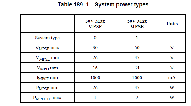
I am not sure about my mistake on the MPD power. The number is listed in table 189-9

So if I were a design engineer to implement this, I would have checked my total load requirement. If it is 16W, I would choose type 0. if I need just 1 W more, I would have
to bump up to type 1. So increasing VMPSE(min), therefore higher guaranteed MPSE power does not really help me. Even if VMPSE(min) is 26V and MPSE
and MPD are next to each other so 0 voltage drop between them, technically MPD can pull full 26W(26V x 1A) from MPSE, but I still can not do that without change on table 189-9 at the same time, because my design is limited by PMPD in table 189-9, not PMPSE
in table 189-1. Did I misunderstand anything here?
General
From: Chad Jones (cmjones) <cmjones@xxxxxxxxx>
Sent: Wednesday, January 8, 2025 11:56 AM
To: Zach Pan <zach.pan@xxxxxx>; STDS-802-3-SPMD@xxxxxxxxxxxxxxxxx
Subject: Re: D2.0 comments 297 and 269
[External email: Use caution with links and attachments]
Zach, discussion here is encouraged, thanks for your reply.
You are correct in that I left out the power lost to the cable in my rough estimates for MPD power. That additional loss further exacerbates problem, as incremental power is allocated to the mixing segment.
This means the numbers in my previous email are best case numbers…
You are mistaken to use the min MPD voltage to calculate MPD power. I was also careful to state I was talking about guaranteed MPSE power. The Min MPD voltage is what the last MPD on the mixing segment might
see, but not what every MPD will see. It hurts the head at times to think about this as the number of elements get hard to juggle. I’ve assembled a spreadsheet to help better estimate what a system might get per PD, I expect to write an annex at some point
and post that spreadsheet on the 802.3 site which 802.3 customers could use to help better engineer their system. It’s part of a bigger issue I have with the draft and unit loads, but that’s a whole other rathole that I will avoid right now.
Restricting the minimum MPSE voltage isn’t a burden on MPDs or MPSEs. It’s a burden on the power supply one might use to power the MPSE. My recollection of the discussion over time was that it’s a small burden
to insist the MPSE supply has a tighter “minus” tolerance than to cripple every installation by making the lower limit artificially low. What’s the reality that you’ll encounter a “24 V system” at 21.6 volts?
Regards,
Chad Jones
Principal Engineer, Cisco Systems
Executive Secretary, IEEE 802.3 Working Group
Chair, IEEE P802.3da Task Force
Principal, NFPA 70 CMP3
Newbie here. Not sure if I am supposed to reply to this email or use a different channel for my comments. Please let me know.
This is a topic that Schneider are closely followed. In our industrial drive or other equipment, 24V is a commonly used auxiliary power supply voltage, with a typical tolerance
band of -10% to +20%, which translates to 21.6Vmin and 28.8V max. So, we appreciate the comment that calls out that change. Otherwise, it will break the voltage compatibility and require us to add some unnecessary circuit to satisfy a 26V VMPSE(min).
As for the concerns of max power for MPD. It is limited by VMPD(min) and IMPSE(min), which is 16V and 1A in the draft D2.0. 16 W is the limit of type 0 configuration anyway,
and the user are supposed to use type 1 for higher power anyway. So I don’t see the change of VMPSE(min) have any negative impact on that.
Of course. The large gap between VMPSE(min) and VMPD(min) would allows longer wire and higher resistance drop on the wire. The proposed change would reduce the voltage drop
allowed on the wire from 10V to 5.6 V, which means the max wire resistance allowed changes from 10Ohm to 5.6 Ohm. I don’t see that as a problem, but we could specify a minimum wire size for given wire length to guarantee that is meet.

|
Best regards,
Zach Pan
|
|
|
Power Electronics Expert
Energy Management Business
Schneider Electric
|
M +1-714-876-4980
E zach.pan@xxxxxx
MS TEAMS zach.pan@xxxxxx
|
|
 1101
Shiloh Glenn Dr, Suite 100, Morrisville, NC 27560, United States 1101
Shiloh Glenn Dr, Suite 100, Morrisville, NC 27560, United States
|

|
[External email: Use caution with links and attachments]
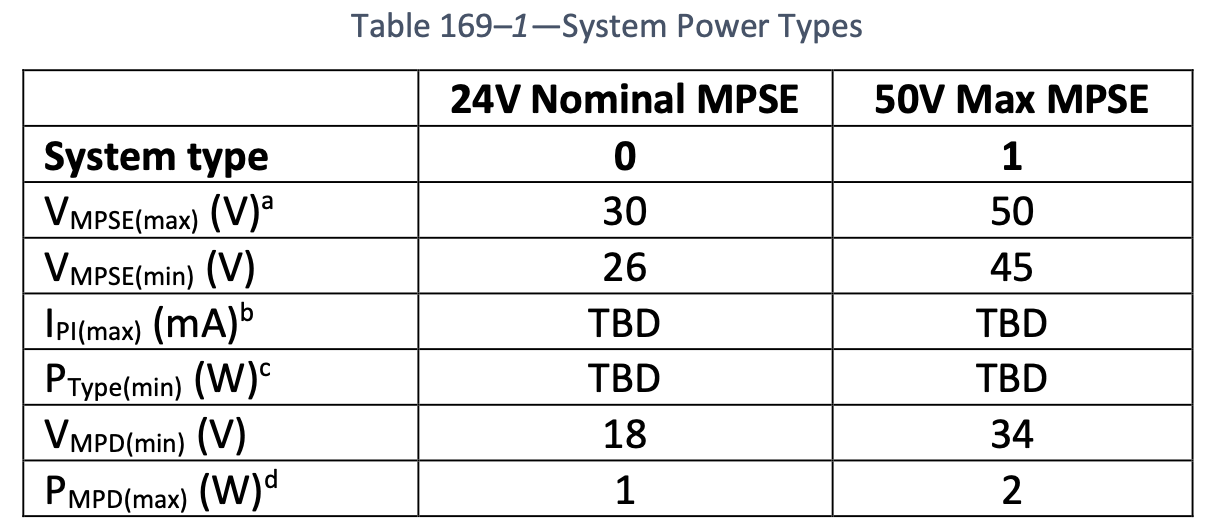
These two comments assert that the VMPSEmin voltage should not be 26 V but instead should be 21.6 V. I dug through the history and this text was added in Nov 2023, via this presentation:
https://www.ieee802.org/3/da/public/1123/clause169_clean.pdf (though there is a presentation there with markups and I don’t recall if this is something we marked up during the meeting
and imported the edited version:
https://www.ieee802.org/3/da/public/1123/clause169_edits.pdf). Regardless of which file was used, Table 169-1 is the same in both locations:

So VMPSEmin has been 26 V from the start. I’m opposed to lowering the minimum voltage because that will then also lower the guaranteed MPSE power. The average power available to an MPD is already low (26 V
* 1 A / 16 nodes = 1.625 W), the change to 21.6 would reduce by about a quarter watt per MPD, or about 17%. I’ve stated many times, the one complaint we will get after publication is “how do I get more power, I need X more watts for my application.” I’m very
focused on optimizing power delivered to prevent a follow-on standard only to raise the power.
I’d expect a presentation justifying 21.6 V and it will take convincing 75% of the TF to make this change. I will not be one of those 75%.
Regards,
Chad Jones
Principal Engineer, Cisco Systems
Executive Secretary, IEEE 802.3 Working Group
Chair, IEEE P802.3da Task Force
Principal, NFPA 70 CMP3
To unsubscribe from the STDS-802-3-SPMD list, click the following link:
https://listserv.ieee.org/cgi-bin/wa?SUBED1=STDS-802-3-SPMD&A=1
To unsubscribe from the STDS-802-3-SPMD list, click the following link:
https://listserv.ieee.org/cgi-bin/wa?SUBED1=STDS-802-3-SPMD&A=1
To unsubscribe from the STDS-802-3-SPMD list, click the following link: https://listserv.ieee.org/cgi-bin/wa?SUBED1=STDS-802-3-SPMD&A=1
To unsubscribe from the STDS-802-3-SPMD list, click the following link: https://listserv.ieee.org/cgi-bin/wa?SUBED1=STDS-802-3-SPMD&A=1
|


