Steve,
But also realize that the general line
also has built in margin for it to account for temperature, environmental, and material
variation as well. The line as currently proposed has to be examined to
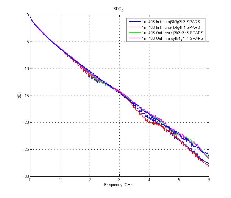
look at from several aspects. For example, the Molex channels are hugging
the new proposed 23 dB line. 5” are on the daughtercard and 35”
are on the backplane, which uses a typical 7 mil line. So we are saying
that to meet the skin effect at the lower frequencies we need a 7 mil wide line?
I think that is too far. Look at the attached figure – 7 mil wide
traces hug that line. I think we have moved it too far upward.
I don’t see any efforts yet on
reducing the problem via the crosstalk aspect of the problem. Has that
been abandoned? I don’t think all of the burden at this time should
be shifted to the channel, but should also be shared with the total allowable crosstalk.
Many of the channels did have margin. We should look to striking a
balance between the two.
John
-----Original Message-----
From: Steve Anderson
[mailto:steve.anderson@xilinx.com]
Sent: Monday, January 16, 2006
2:52 PM
To: DAmbrosia, John F;
STDS-802-3-BLADE@listserv.ieee.org
Subject: RE: [BP] Interference
tolerance test channels
John, all:
But does a line made with the squared and cubed terms create a physically
realizable channel?
In the real channel I think there may be only two variables to play with:
skin effect and dielectric
absorption. If we
base simulations on something other than this, then I think bad things can
happen like
non-causal effects.
Steve A.
From:
DAmbrosia, John F [mailto:john.dambrosia@tycoelectronics.com]
Sent: Monday, January 16, 2006
1:34 PM
To:
STDS-802-3-BLADE@listserv.ieee.org
Subject: Re: [BP] Interference
tolerance test channels
Guys,
Goergen asked the magic
question. Is it possible? Yes it is. We have a squared and
cubed term to play with. I am hoping Joel has some suggestions as
well. I just had a chance to do a quick scan and saw this. I will
be working on this stuff tonight
John
-----Original Message-----
From: Oganessyan, Gourgen [mailto:Gourgen.Oganessyan@MOLEX.COM]
Sent: Monday, January 16, 2006
2:24 PM
To:
STDS-802-3-BLADE@listserv.ieee.org
Subject: Re: [BP] Interference
tolerance test channels
I see
now what you refer too. I am not sure how you physically relaize a channel you
are suggesting, keep low freq the same and come up at 5 GHz? Any physical
channel should result in a tilted line?
-----Original
Message-----
From: Mellitz, Richard
[mailto:richard.mellitz@INTEL.COM]
Sent: Monday, January 16, 2006 1:05
PM
To:
STDS-802-3-BLADE@listserv.ieee.org
Subject: Re: [BP] Interference
tolerance test channels
The line didn’t only tilt. It also shifted. John D looked
at a few channels as I attached. If we shift, it’s got an impact for KX
and KX4.
…Rich
From: Joe M
Abler [mailto:abler@US.IBM.COM]
Sent: Monday, January 16, 2006
1:15 PM
To:
STDS-802-3-BLADE@listserv.ieee.org
Subject: Re: [BP] Interference
tolerance test channels
The new channel appears to be inline with what we stated - a tilt of the
line from DC to about a 3dB drop at 5GHz. Why do you feel the lower
frequencies need to stay fixed?
Thanks, Joe
Joe Abler
abler@us.ibm.com
IBM Systems & Technology Group
919-254-0573
High Speed Serial Link Solutions
919-254-9616 (fax)
3039 Cornwallis Road
Research Triangle Park, NC 27709
|
|
"Mellitz, Richard"
<richard.mellitz@INTEL.COM>
01/16/2006
10:41 AM
Please
respond to "Mellitz, Richard"
|
To:
STDS-802-3-BLADE@listserv.ieee.org
cc:
Subject: Re: [BP]
Interference tolerance test channels
|
Hi Charles,
DC and low freq's went down way to much! Can you create a model with the
same losses at say 1GHz or so and 2 dB less at 5GHz? I thought that's
what we agreed.
... Rich
-----Original Message-----
From: Charles Moore [mailto:charles.moore@avagotech.com]
Sent: Friday, January 13, 2006 8:42 PM
To: STDS-802-3-BLADE@listserv.ieee.org
Subject: [BP] Interference tolerance test channels
guys,
I propose that we use the model ITTC_23.s4p for reduced
attenuation
EIT modeling. If it really will not work, ITTC_20.s4p is available as a
bail out channel. If it looks too easy, let me know and i will step it
up just
a tad.
The numbers refer to the fitted attenuation at 5.15...GHz.
charles
--
|--------------------------------------------------------------------|
| Charles Moore
| Avago Technologies
| Image Solutions Division
| charles.moore@avagotech.com
| (970) 288-4561
|--------------------------------------------------------------------|