Hi Mike,
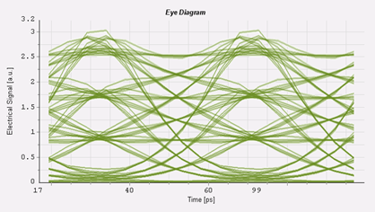
I don’t have a clear theoretical explanation, rather than CD should generate spread of the queues of the impulse and peaking at the center.
I’ve been checking with some people in Cisco, usually we see this under different simulations environment where you can define the TX characteristics (e.g. VPI).
Below a snapshot I got from people using this tool: it’s a 25.8Gbaud PAM4 eye after propagation into 100ps/nm dispersion, which is quite similar effect we are measuring.

I’ve been trying to check on the IEEE spreadsheet model by using the 10GBASE-ER (1550S40km) and actually there’s no change in the crossing points.
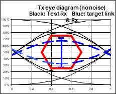
I run the model with 80kms link and this is the eye I got, which looks like ‘just’ a filtered eye where a LP filter is applied (no crossing points variations).

Looking into IEEE spreadsheet formulas is not easy, so maybe someone who worked deeply into it can try to cross-check the consistence of this model versus the commercially
available ones ?
Best regards
Marco
From: Mike Dudek <mdudek@xxxxxxxxxxx>
Sent: miércoles, 3 de julio de 2019 20:48
To: Marco Mazzini (mmazzini) <mmazzini@xxxxxxxxx>; STDS-802-3-100G-OPTX@xxxxxxxxxxxxxxxxx
Subject: RE: P802.3cu Task Force ad hoc meeting
Thanks for the explanation. Everything you say makes sense to me, however I’m still wondering how chromatic dispersion is creating the NRZ eyes you show below.
From: Marco Mazzini (mmazzini) <00000e5c2535a1ca-dmarc-request@xxxxxxxx>
Sent: Wednesday, July 3, 2019 10:19 AM
To: STDS-802-3-100G-OPTX@xxxxxxxxxxxxxxxxx
Subject: [EXT] Re: [802.3_100G-OPTX] P802.3cu Task Force ad hoc meeting
External Email
Hi Mike,
thank you for your question.
I think in this experiment it’s just chromatic dispersion which tends to spread the impulse frequencies and get the eye crossing points compressed towards the bottom.
I put below an example of an NRZ eye behavior for at 10Gb/s under chromatic dispersion, starting with 50% crossing points in back-to-back (left to right: BTB, 400 and 800ps/nm).

So if we consider a PAM4 eye that would suffer the same kind of distortion that we actually measured over different CD values, having less phase/amplitude margins on the top eye make sense to
me.
This penalty is then partially recovered by the equalizer, but is where the bottom compression seem to make good job (I think optimum threshold for the mid-eye should move away from 50%, as well
the bottom eye would go more towards the 0 level, so a real receiver, not coerced to 1% threshold optimization should work better than the reference one).
As reported in slide 4, in the experiment I tried to keep myself always in the same identical input power for the PDFA pre-amplifier to avoid different noise on 2-3 levels (for this I always report
36dB OSNR for all test conditions).
As well I tried to ensure the input power to the fiber to be small enough (having
» 0dBm at TP2, I got max -1dBm into fiber when VOA=0, which correspond to the highest fiber loss case) to avoid SPM.
I also avoided to use narrow BW optical filter, which can also cause crossing points to drop too, paying a bit of penalty on overall system noise, but ensuring I wasn’t overstressing the system.
Hope this answer your question, please let me know if there’s something that I can do to improve for the next experiments in case.
Best regards
Marco
From: Mike Dudek <mdudek@xxxxxxxxxxx>
Sent: miércoles, 3 de julio de 2019 18:17
To: Mark Nowell (mnowell) <mnowell@xxxxxxxxx>; 100G OPTX <stds-802-3-100G-OPTX@xxxxxxxxxxxxxxxxx>; Marco Mazzini (mmazzini) <mmazzini@xxxxxxxxx>
Subject: RE: P802.3cu Task Force ad hoc meeting
Thanks for a very interesting presentation Marco. I was hoping to ask the following question as a follow up to Paul Kolesar’s but there wasn’t time. I’m interested to know what property
of the transmitter/fiber chromatic dispersion causes the top eye to be degraded more than the bottom eye (and hence the bottom compensation works). I’m assuming you made sure that it wasn’t anything to do with the PDFA. I agree that ensuring the input
to the PDFA was the same in all cases is a very good start. The fact that the bottom compensation degraded the result with the short fibers also implies to me that it probably isn’t a PDFA issue.
-----Original Appointment-----
From: Mark Nowell (mnowell) <mnowell@xxxxxxxxx>
Sent: Monday, May 27, 2019 9:31 AM
To: Mark Nowell (mnowell); 100G OPTX
Subject: [EXT] [802.3_100G-OPTX] P802.3cu Task Force ad hoc meeting
When: Wednesday, July 3, 2019 11:00 AM-12:00 PM (UTC-05:00) Eastern Time (US & Canada).
Where:
External Email
-- Do not delete or change any of the following text. --
|
|
|
Meeting number (access code): 205 545 351
Meeting password: c94Dmhrn (29436476 from phones)
Join from a video system or application
Dial
205545351@xxxxxxxxxxxxxxx
You can also dial 173.243.2.68 and enter your meeting number.
From the Cisco internal network, dial *267* and the 9-digit meeting number. If you are the host, enter your PIN when prompted.
Join by phone
+1-866-432-9903 Call-in
toll-free number (US/Canada)
+1-408-525-6800 Call-in
toll number (US/Canada)
Global call-in numbers | Toll-free
calling restrictions
Can't join the meeting?
If you are a host, go here to view
host information.
IMPORTANT NOTICE: Please note that this Webex service allows audio and other information sent during the session to be recorded, which may be discoverable
in a legal matter. By joining this session, you automatically consent to such recordings. If you do not consent to being recorded, discuss your concerns with the host or do not join the session.
To unsubscribe from the STDS-802-3-100G-OPTX list, click the following link:
https://listserv.ieee.org/cgi-bin/wa?SUBED1=STDS-802-3-100G-OPTX&A=1
To unsubscribe from the STDS-802-3-100G-OPTX list, click the following link:
https://listserv.ieee.org/cgi-bin/wa?SUBED1=STDS-802-3-100G-OPTX&A=1
To unsubscribe from the STDS-802-3-100G-OPTX list, click the following link: https://listserv.ieee.org/cgi-bin/wa?SUBED1=STDS-802-3-100G-OPTX&A=1