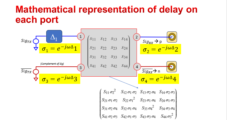
The method of introducing Skew in my case involves:
Based on measurements identify basic profiles in Freq domain that are combined to represent measured s-parameters then add that combined profile to the end-to-end freq domain s-parameters
Cables , pcb, packages and even silicon analog paths etc. may have their own profiles towards combined profile.
i.e., in Rich’s equation
∆ is varying over
![]() and
this is introduced in s-param block in each direction and not per port.
and
this is introduced in s-param block in each direction and not per port.
at present measurements show lot more skew than what we can afford for 224G , limiting
∆ to channel sub-components can achieve in terms of skew.
For example, Cable vendors may guide us for 224G application what we can use as a limit over all freq range of interest– say 1 ps/m or whatever.
-Upen
From: Richard Mellitz <000014533bad0b9c-dmarc-request@xxxxxxxxxxxxxxxxx>
Sent: Thursday, June 20, 2024 10:53 AM
To: STDS-802-3-B400G-ELEC@xxxxxxxxxxxxxxxxx
Subject: Re: [802.3_B400G_ELEC] [802.3dj] 20 June electrical ad hoc - response to request for more details
FYI: This is what how delay was added to a channel in the COM code.

|
From: Upen Reddy Kareti (ureddy) <00000d999961d690-dmarc-request@xxxxxxxxxxxxxxxxx>
Sent: Thursday, June 20, 2024 1:02 PM
To: STDS-802-3-B400G-ELEC@xxxxxxxxxxxxxxxxx
Subject: [802.3_B400G_ELEC] [802.3dj] 20 June electrical ad hoc - response to request for more details
|
Caution: This email originated from outside the organization. Do not click links or open attachments unless you recognize the sender and know the content is safe.
|
Hi All,
Two requests were made during my presentation today– here are my responses
1> provide a link to my skew presentation – the following link is added to today’s presentation.
-
Identifying basic skew profiles in freq. domain slide 13 of
kareti_3dj_02_2401.pdf – actual step by step procedure how to add skew is not shared
2> Max tap values for under 40 dB insertion Loss – separate stats for the ones passing COM of 3 dB and the ones not passing of 3 dB.
-
note the following data is not as relevant once we start using COM code 4.6.3 as fixes are provided for tap location reporting issue.
- Also, when we configure with TX FFE and g_DC >0 setups.
For a case with post cursors of 8 fixed 3 banks (of 4 taps in each bank ) RX FFE span up to 100 UI and Package class B for both Transmitter and
Receiver:
Channels < 40 dB and passing 3dB COM.


Channels < 40 dB and failing 3dB COM.


Regards
Upen
To unsubscribe from the STDS-802-3-B400G-ELEC list, click the following link:
https://listserv.ieee.org/cgi-bin/wa?SUBED1=STDS-802-3-B400G-ELEC&A=1
To unsubscribe from the STDS-802-3-B400G-ELEC list, click the following link:
https://listserv.ieee.org/cgi-bin/wa?SUBED1=STDS-802-3-B400G-ELEC&A=1
To unsubscribe from the STDS-802-3-B400G-ELEC list, click the following link: https://listserv.ieee.org/cgi-bin/wa?SUBED1=STDS-802-3-B400G-ELEC&A=1