Sent: Wednesday, July 17, 2024 11:00 AM
To: STDS-802-3-B400G-OPTX@xxxxxxxxxxxxxxxxx <STDS-802-3-B400G-OPTX@xxxxxxxxxxxxxxxxx>
All,
While I appreciate the benefits of us looking to the future, at this point we have not selected a 400G per lane (assuming based on PAM4)based solution, let’s be careful with our discussions so that people do not think we are now considering adding objectives.
As IEEE P802.3dj already has enough PMDs to resolve I would suggest we focus future needs discussion elsewhere, such as the NEA.
Regards,
John
From: Frank J Effenberger <frank.effenberger@xxxxxxxxxxxxx>
Sent: Wednesday, July 17, 2024 1:44 PM
To: STDS-802-3-B400G-OPTX@xxxxxxxxxxxxxxxxx
Subject: Re: [802.3_B400G_OPTX] Dispersion for 400G lanes
All,
Before we start proposing such innovative ideas, can we have a level set on what it is we are trying to achieve?
I mean, 400G per wave means 4 times less dispersion than 200G. 4 is a big number. I think it is very unlikely that fiber specs are going to achieve that much improvement, no matter what you do. But, what is it that we are trying to do?
Are we talking of an FR4 or an LR4 kind of link, and what wavelength plan?
Thanks,
Frank E.
From: Parsons, Earl <00002109e8f11cc7-dmarc-request@xxxxxxxxxxxxxxxxx>
Sent: Wednesday, July 17, 2024 10:58 AM
To: STDS-802-3-B400G-OPTX@xxxxxxxxxxxxxxxxx
Subject: [802.3_B400G_OPTX] Dispersion for 400G lanes
Hi All,
Here’s a new thread for the dispersion considerations for 400G lanes.
If we want new CD fiber specs for 400G lanes, now is the right time to start those conversations.
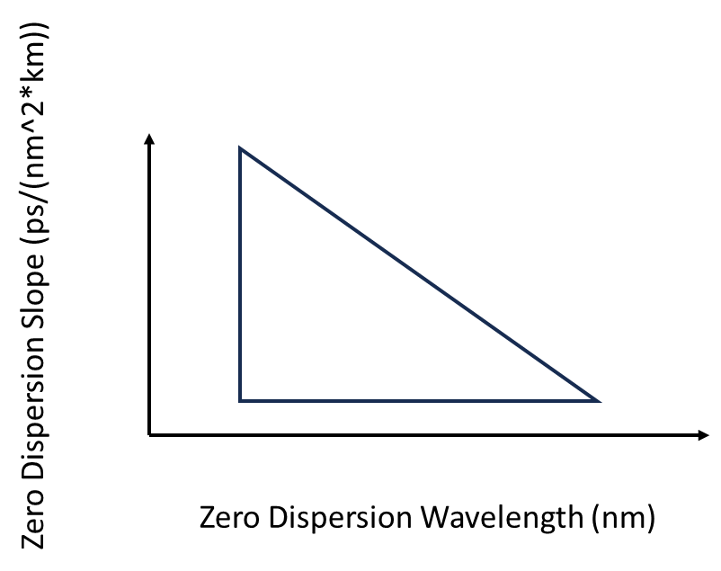
For multimode CD specs we limit the range of wavelength and slope together. For example, the OM4 standard has a triangular region of compliant wavelengths and slopes that looks something like this:

For SM we might want to consider a trapezoid shape like this:

I think it would be easier for fiber manufacturers to comply with this shape with their existing product than narrowing the zero-dispersion wavelength range like Chris proposed earlier on the reflector. Snipping of the top “corners” of the CD spec range could give the same reduction in max/min dispersion.
We could also take a page from IEC connector standards. For different connector grades IEC specifies random mate connector attenuation such that “probability of a random mated connector set of meeting or exceeding the specified level of attenuation will be ≥ 97 %.” A new fiber standard could specify that >99% of a manufacturer’s fibers fall within the trapezoid.
Thanks.
- Earl
To unsubscribe from the STDS-802-3-B400G-OPTX list, click the following link: https://listserv.ieee.org/cgi-bin/wa?SUBED1=STDS-802-3-B400G-OPTX&A=1 [listserv.ieee.org]
To unsubscribe from the STDS-802-3-B400G-OPTX list, click the following link: https://listserv.ieee.org/cgi-bin/wa?SUBED1=STDS-802-3-B400G-OPTX&A=1 [listserv.ieee.org]
To unsubscribe from the STDS-802-3-B400G-OPTX list, click the following link: https://listserv.ieee.org/cgi-bin/wa?SUBED1=STDS-802-3-B400G-OPTX&A=1
To unsubscribe from the STDS-802-3-B400G-OPTX list, click the following link: https://listserv.ieee.org/cgi-bin/wa?SUBED1=STDS-802-3-B400G-OPTX&A=1