|
Parameter
|
Phase= 0
|
Phase= 24
|
|
TDECQ_fixed
|
6.39 dB
|
2.70 dB
|
|
TDECQ_search
|
4.06 dB
|
1.62 dB
|
|
Ceq
|
4.06 dB
|
1.62 dB
|
|
OMA_TDECQ
|
0.417
|
0.688
|
|
DFE
|
0.33
|
0.19
|
|
sigmaG
|
0.010
|
0.017
|
Sent: Tuesday, July 14, 2026 6:26 AM
To: STDS-802-3-B400G-OPTX@xxxxxxxxxxxxxxxxx <STDS-802-3-B400G-OPTX@xxxxxxxxxxxxxxxxx>
Subject: Re: [802.3_B400G_OPTX] [EXTERNAL] RE: [**EXTERNAL**] RE: IEEE 802.3 TDECQ: Clarification on Histogram Window positioning
CAUTION: EXTERNAL EMAIL
|
Phase
|
Phase0 [UI]
|
PhaseHist [UI]
|
Delta UI [UI]
|
TDECQ_fixed [dB]
|
TDECQ_search [dB]
|
Delta TDECQ [dB]
|
|
0
|
0.000
|
0.925
|
-0.075
|
6.39
|
4.06
|
-2.33
|
|
1
|
0.040
|
0.080
|
0.040
|
5.91
|
5.07
|
-0.84
|
|
2
|
0.080
|
0.160
|
0.080
|
4.95
|
4.85
|
-0.10
|
|
3
|
0.120
|
0.140
|
0.020
|
4.36
|
4.26
|
-0.09
|
|
4
|
0.160
|
0.225
|
0.065
|
4.05
|
3.96
|
-0.09
|
|
5
|
0.200
|
0.220
|
0.020
|
3.90
|
3.82
|
-0.08
|
|
6
|
0.240
|
0.240
|
0.000
|
3.75
|
3.75
|
0.00
|
|
7
|
0.280
|
0.280
|
0.000
|
3.81
|
3.81
|
0.00
|
|
8
|
0.320
|
0.280
|
-0.040
|
3.84
|
3.84
|
0.00
|
|
9
|
0.360
|
0.320
|
-0.040
|
3.89
|
3.81
|
-0.08
|
|
10
|
0.400
|
0.300
|
-0.100
|
3.97
|
3.89
|
-0.08
|
|
11
|
0.440
|
0.340
|
-0.100
|
4.02
|
3.94
|
-0.09
|
|
12
|
0.480
|
0.400
|
-0.080
|
4.04
|
4.04
|
0.00
|
|
13
|
0.520
|
0.500
|
-0.020
|
3.99
|
3.99
|
0.00
|
|
14
|
0.560
|
0.640
|
0.080
|
4.08
|
4.02
|
-0.05
|
|
15
|
0.600
|
0.620
|
0.020
|
4.17
|
4.12
|
-0.06
|
|
16
|
0.640
|
0.640
|
0.000
|
4.66
|
4.66
|
0.00
|
|
17
|
0.680
|
0.780
|
0.100
|
4.87
|
4.80
|
-0.07
|
|
18
|
0.720
|
0.820
|
0.100
|
5.21
|
4.84
|
-0.37
|
|
19
|
0.760
|
0.860
|
0.100
|
5.24
|
4.27
|
-0.97
|
|
20
|
0.800
|
0.900
|
0.100
|
5.11
|
3.70
|
-1.41
|
|
21
|
0.840
|
0.925
|
0.085
|
4.77
|
3.37
|
-1.40
|
|
22
|
0.880
|
0.925
|
0.045
|
3.86
|
3.13
|
-0.73
|
|
23
|
0.920
|
0.925
|
0.005
|
3.08
|
2.85
|
-0.23
|
|
24
|
0.960
|
0.025
|
0.065
|
2.70
|
1.62
|
-1.08
|
|
Phase
|
Phase0 [UI]
|
PhaseHist [UI]
|
Delta UI [UI]
|
TDECQ_fixed [dB]
|
TDECQ_search [dB]
|
Delta TDECQ [dB]
|
|
6
|
0.240
|
0.240
|
0.000
|
3.75
|
3.75
|
0.00
|
|
7
|
0.280
|
0.280
|
0.000
|
3.81
|
3.81
|
0.00
|
|
12
|
0.480
|
0.400
|
-0.080
|
4.04
|
4.04
|
0.00
|
|
16
|
0.640
|
0.640
|
0.000
|
4.66
|
4.66
|
0.00
|
|
23
|
0.920
|
0.925
|
0.005
|
3.08
|
2.85
|
-0.23
|
|
Phase
|
Phase0 [UI]
|
PhaseHist [UI]
|
Delta UI [UI]
|
TDECQ_fixed [dB]
|
TDECQ_search [dB]
|
Delta TDECQ [dB]
|
|
16
|
0.640
|
0.640
|
0.000
|
4.66
|
4.66
|
0.00
|
|
17
|
0.680
|
0.780
|
0.100
|
4.87
|
4.80
|
-0.07
|
|
18
|
0.720
|
0.820
|
0.100
|
5.21
|
4.84
|
-0.37
|
|
19
|
0.760
|
0.860
|
0.100
|
5.24
|
4.27
|
-0.97
|
|
20
|
0.800
|
0.900
|
0.100
|
5.11
|
3.70
|
-1.41
|
|
21
|
0.840
|
0.925
|
0.085
|
4.77
|
3.37
|
-1.40
|
|
Phase
|
Phase0 [UI]
|
PhaseHist [UI]
|
Delta UI [UI]
|
TDECQ_fixed [dB]
|
TDECQ_search [dB]
|
Delta TDECQ [dB]
|
|
0
|
0.000
|
0.925
|
-0.075
|
6.39
|
4.06
|
-2.33
|
|
Phase
|
Phase0 [UI]
|
PhaseHist [UI]
|
Delta UI [UI]
|
TDECQ_fixed [dB]
|
TDECQ_search [dB]
|
Delta TDECQ [dB]
|
|
19
|
0.760
|
0.860
|
0.100
|
5.24
|
4.27
|
-0.97
|
|
20
|
0.800
|
0.900
|
0.100
|
5.11
|
3.70
|
-1.41
|
|
21
|
0.840
|
0.925
|
0.085
|
4.77
|
3.37
|
-1.40
|
|
24
|
0.960
|
0.025
|
0.065
|
2.70
|
1.62
|
-1.08
|
Right = PhaseHist + 0.05 UI
Sent: Monday, July 13, 2026 11:34 AM
To: STDS-802-3-B400G-OPTX@xxxxxxxxxxxxxxxxx <STDS-802-3-B400G-OPTX@xxxxxxxxxxxxxxxxx>
Subject: Re: [802.3_B400G_OPTX] [EXTERNAL] RE: [**EXTERNAL**] RE: IEEE 802.3 TDECQ: Clarification on Histogram Window positioning
CAUTION: EXTERNAL EMAIL
Sent: Sunday, July 12, 2026 3:44 PM
To: STDS-802-3-B400G-OPTX@xxxxxxxxxxxxxxxxx <STDS-802-3-B400G-OPTX@xxxxxxxxxxxxxxxxx>
Subject: Re: [802.3_B400G_OPTX] [EXTERNAL] RE: [**EXTERNAL**] RE: IEEE 802.3 TDECQ: Clarification on Histogram Window positioning
CAUTION: EXTERNAL EMAIL
|
This is the first time you received an email from this sender (000014533bad0b9c-dmarc-request@xxxxxxxxxxxxxxxxx). Exercise caution when clicking links, opening attachments or taking further action, before validating its authenticity.
|
Since the measured eye already includes all transmitter jitter and phase 0 is optimized directly through the TDECQ search, what receiver impairment or uncertainty is the histogram intended to model? Without identifying the physical meaning of the histogram, it is difficult to determine whether the histogram center should be tied to phase 0 or treated as an independent optimization variable.
…Rich
|
Sent: Sunday, 12 July 2026 10:09:41
To: STDS-802-3-B400G-OPTX@xxxxxxxxxxxxxxxxx <STDS-802-3-B400G-OPTX@xxxxxxxxxxxxxxxxx>
Subject: Re: [802.3_B400G_OPTX] [EXTERNAL] RE: [**EXTERNAL**] RE: IEEE 802.3 TDECQ: Clarification on Histogram Window positioning
|
You don't often get email from mtdudek@xxxxxxxxx.
Learn why this is important
|
|
⚠ CAUTION:
This email originated from outside the organization. Do not click links or open attachments unless you recognize the sender and know the content is safe.
|
Hi allPlease note that two of my (late, non-ballot) comments address the histogram window and their positions.L09 suggests removing the sentence that can be interpreted as allowing asymmetry. The text of the comment includes the rationale for using symmetrically placed histograms (matching real receiver behavior).L08 suggests removing the nominal width of each histogram window, allowing instead some maximum width. Ideally the width should be 0 to capture a specific phase. This is possible if the signal is captured/interpolated to an integer oversampling ratio.
</Adee>
From: Alloin, Laurent <laurent.alloin@xxxxxxxxxxxxxxxxxxxxxxxx>
Date: Saturday, 11 July 2026 at 22:19
To: Mike Dudek <mdudek@xxxxxxxxxxx>; norm.swenson@xxxxxxxx <norm.swenson@xxxxxxxx>; 'Hansel DSilva' <Hansel.D'Silva@xxxxxxxxxxxxxxxx>; 'Richard Mellitz' <richard.mellitz@xxxxxxxxxx>; Mahadevan, Amitkumar <amahadev@xxxxxxxxx>; 'Roberto Rodes' <roberto.rodes@xxxxxxxxxxxx>; Mark Nowell (mnowell) <mnowell@xxxxxxxxx>; 'Ali Ghiasi' <ali@xxxxxxxxxxxxxxxxx>; Adee Ran (aran) <aran@xxxxxxxxx>; miguangcan@xxxxxxxxxx <miguangcan@xxxxxxxxxx>; 'Adam Gregory' <adam.gregory@xxxxxxxxxx>; 'Heck, Howard' <howard.heck@xxxxxx>; 'Samuel Kocsis' <Samuel.Kocsis@xxxxxxxxxxxxxxxx>; 'Ahmad El-Chayeb' <ahmad.el-chayeb@xxxxxxxxxxxx>
Cc: STDS-802-3-B400G-OPTX@xxxxxxxxxxxxxxxxx <STDS-802-3-B400G-OPTX@xxxxxxxxxxxxxxxxx>; STDS-802-3-B400G-ELEC@xxxxxxxxxxxxxxxxx <STDS-802-3-B400G-ELEC@xxxxxxxxxxxxxxxxx>
Subject: Re: [EXTERNAL] RE: [**EXTERNAL**] RE: IEEE 802.3 TDECQ: Clarification on Histogram Window positioning
Hi Mike,
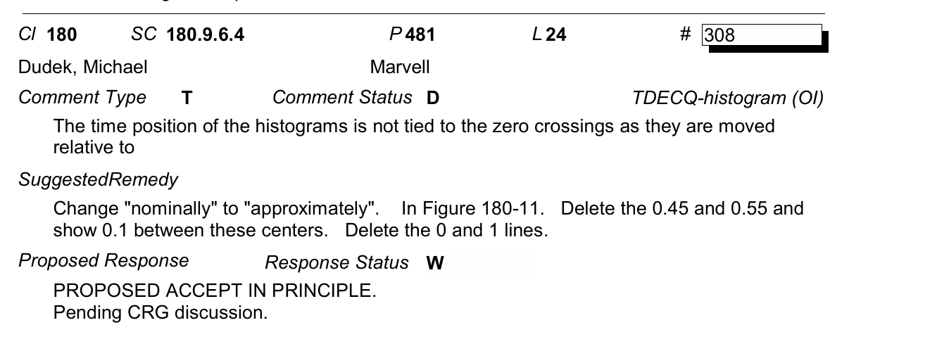
Can you explain then your comment #308 against draft 3.0, in which you proposed to eliminate reference to the 0.45 and 0.55 position of the zero crossing ? I interpreted this suggestion as an acknowledgement that the position of the histogram is not necessarily tied to the middle of the eye, as determined by the sampling phase selected to reconstruct the eye.
Laurent
From: Mike Dudek <mdudek@xxxxxxxxxxx>
Sent: Saturday, July 11, 2026 2:10 PM
To: norm.swenson@xxxxxxxx <norm.swenson@xxxxxxxx>; Alloin, Laurent <laurent.alloin@xxxxxxxxxxxxxxxxxxxxxxxx>; 'Hansel DSilva' <Hansel.D'Silva@xxxxxxxxxxxxxxxx>; 'Richard Mellitz' <richard.mellitz@xxxxxxxxxx>; Mahadevan, Amitkumar <amahadev@xxxxxxxxx>; 'Roberto Rodes' <roberto.rodes@xxxxxxxxxxxx>; 'Mark Nowell (mnowell)' <mnowell@xxxxxxxxx>; 'Ali Ghiasi' <ali@xxxxxxxxxxxxxxxxx>; 'Adee Ran (aran)' <aran@xxxxxxxxx>; miguangcan@xxxxxxxxxx <miguangcan@xxxxxxxxxx>; 'Adam Gregory' <adam.gregory@xxxxxxxxxx>; 'Heck, Howard' <howard.heck@xxxxxx>; 'Samuel Kocsis' <Samuel.Kocsis@xxxxxxxxxxxxxxxx>; 'Ahmad El-Chayeb' <ahmad.el-chayeb@xxxxxxxxxxxx>
Cc: STDS-802-3-B400G-OPTX@xxxxxxxxxxxxxxxxx <STDS-802-3-B400G-OPTX@xxxxxxxxxxxxxxxxx>; STDS-802-3-B400G-ELEC@xxxxxxxxxxxxxxxxx <STDS-802-3-B400G-ELEC@xxxxxxxxxxxxxxxxx>
Subject: Re: [EXTERNAL] RE: [**EXTERNAL**] RE: IEEE 802.3 TDECQ: Clarification on Histogram Window positioningI agree with Norm's interpretation and also have a comment to delete "nominally".
From: norm.swenson@xxxxxxxx <norm.swenson@xxxxxxxx>
Sent: Saturday, July 11, 2026 09:03
To: 'Alloin, Laurent' <laurent.alloin@xxxxxxxxxxxxxxxxxxxxxxxx>; 'Hansel DSilva' <Hansel.D'Silva@xxxxxxxxxxxxxxxx>; 'Richard Mellitz' <richard.mellitz@xxxxxxxxxx>; Mike Dudek <mdudek@xxxxxxxxxxx>; 'Mahadevan, Amitkumar' <amahadev@xxxxxxxxx>; 'Roberto Rodes' <roberto.rodes@xxxxxxxxxxxx>; 'Mark Nowell (mnowell)' <mnowell@xxxxxxxxx>; 'Ali Ghiasi' <ali@xxxxxxxxxxxxxxxxx>; 'Adee Ran (aran)' <aran@xxxxxxxxx>; miguangcan@xxxxxxxxxx <miguangcan@xxxxxxxxxx>; 'Adam Gregory' <adam.gregory@xxxxxxxxxx>; 'Heck, Howard' <howard.heck@xxxxxx>; 'Samuel Kocsis' <Samuel.Kocsis@xxxxxxxxxxxxxxxx>; 'Ahmad El-Chayeb' <ahmad.el-chayeb@xxxxxxxxxxxx>
Cc: STDS-802-3-B400G-OPTX@xxxxxxxxxxxxxxxxx <STDS-802-3-B400G-OPTX@xxxxxxxxxxxxxxxxx>; STDS-802-3-B400G-ELEC@xxxxxxxxxxxxxxxxx <STDS-802-3-B400G-ELEC@xxxxxxxxxxxxxxxxx>
Subject: [EXTERNAL] RE: [**EXTERNAL**] RE: IEEE 802.3 TDECQ: Clarification on Histogram Window positioningPrioritize security for external emails:Confirm sender and content safety before clicking links or opening attachmentsHi Laurent
Adding the reflectors to try to save time discussing this at the face-to-face meeting.
The sentences under discussion in D3.1 are:
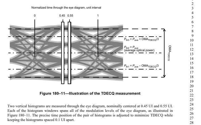
“Two vertical histograms are measured through the eye diagram, nominally centered 0.05 UI before and after sampling phase \phi_0 … The precise time position of the pair of histogram windows is adjusted to minimize TDECQ while keeping the histogram windows spaced 0.1 UI apart."
I do agree that the second sentence was in D3.0 and I recall discussing the meaning of it with you in Munich. I interpret that sentence a bit differently than you do. You believe this means optimizing the taps at \phi_0 then sliding the two histogram windows across the entire \phi_0 -T/2 to \phi_0 + T/2 range to find their optimal location. (Please restate if I have not stated your position accurately.) I interpret those sentences to place the histogram windows, separated by 0.1UI, approximately centered at \phi_0 (from the word nominally) and make fine adjustments as necessary to optimize the symbol error rate. I do not interpret that to mean sliding the center of the windows across the entire unit interval.
I am interested in how others interpret those sentences. Again, since we are searching for the best \phi_0, I don’t think this adjustment of the histogram locations is necessary, which is why I have comments suggesting that the word “nominally” and the second sentence should be deleted. But if others disagree, I think we should try to make the meaning of those sentences clear so that there is no ambiguity in how it should be interpreted.
Regards,
Norm
From: Alloin, Laurent <laurent.alloin@xxxxxxxxxxxxxxxxxxxxxxxx>
Sent: Friday, July 10, 2026 6:37 PM
To: norm.swenson@xxxxxxxx; 'Hansel DSilva' <Hansel.D'Silva@xxxxxxxxxxxxxxxx>; 'Richard Mellitz' <richard.mellitz@xxxxxxxxxx>; 'Mike Dudek' <mdudek@xxxxxxxxxxx>; Mahadevan, Amitkumar <amahadev@xxxxxxxxx>; 'Roberto Rodes' <roberto.rodes@xxxxxxxxxxxx>; 'Mark Nowell (mnowell)' <mnowell@xxxxxxxxx>; 'Ali Ghiasi' <ali@xxxxxxxxxxxxxxxxx>; 'Adee Ran (aran)' <aran@xxxxxxxxx>; miguangcan@xxxxxxxxxx; 'Adam Gregory' <adam.gregory@xxxxxxxxxx>; 'Heck, Howard' <howard.heck@xxxxxx>; 'Samuel Kocsis' <Samuel.Kocsis@xxxxxxxxxxxxxxxx>; 'Ahmad El-Chayeb' <ahmad.el-chayeb@xxxxxxxxxxxx>
Subject: Re: [**EXTERNAL**] RE: IEEE 802.3 TDECQ: Clarification on Histogram Window positioning
Yes, Norm,
I think that this degree of freedom has been part of the specification for a long time, and the zero-crossing reference in the figure was obsolete for some time. I must admit it was before my time, but I see that this degree of freedom brings benefit when the transmitter has group delay distortion or when equalized eyes show some nonlinear skew, which a well-designed receiver can take advantage of. But foremost, I believe that at this point, we do not want to change the measurement results of the TDECQ specification as compared to what it yields prior to the effort of rewriting the specification for clarity, which I think was your goal in Draft D3.1.
Laurent
PS: The exert of D3.0 spells out clearly that this degree of freedom exists in the prior specification.
From: norm.swenson@xxxxxxxx <norm.swenson@xxxxxxxx>
Sent: Friday, July 10, 2026 7:32 PM
To: Alloin, Laurent <laurent.alloin@xxxxxxxxxxxxxxxxxxxxxxxx>; 'Hansel DSilva' <Hansel.D'Silva@xxxxxxxxxxxxxxxx>; 'Richard Mellitz' <richard.mellitz@xxxxxxxxxx>; 'Mike Dudek' <mdudek@xxxxxxxxxxx>; Mahadevan, Amitkumar <amahadev@xxxxxxxxx>; 'Roberto Rodes' <roberto.rodes@xxxxxxxxxxxx>; 'Mark Nowell (mnowell)' <mnowell@xxxxxxxxx>; 'Ali Ghiasi' <ali@xxxxxxxxxxxxxxxxx>; 'Adee Ran (aran)' <aran@xxxxxxxxx>; miguangcan@xxxxxxxxxx <miguangcan@xxxxxxxxxx>; 'Adam Gregory' <adam.gregory@xxxxxxxxxx>; 'Heck, Howard' <howard.heck@xxxxxx>; 'Samuel Kocsis' <Samuel.Kocsis@xxxxxxxxxxxxxxxx>; 'Ahmad El-Chayeb' <ahmad.el-chayeb@xxxxxxxxxxxx>
Subject: RE: [**EXTERNAL**] RE: IEEE 802.3 TDECQ: Clarification on Histogram Window positioning
HI Laurent
Do you interpret that line to mean that you choose a \phi_0 (at which you optimize the taps), you place the windows at \phi_0 +/- .04T and measure TDECQ there, then you scan the center of those windows across the entire range of 0 to T, but keep the same \phi_0 for the tap optimization purposes? That adds yet another parameter to search over and I am not sure that buys us anything.
I believe the original TDEC or TDECQ did not have that in there, as they assumed zero crossings defined 0UI and 1UI, and the histograms were placed around the midpoint between 0UI and 1UI. So I am not so sure that that wisdom would apply here.
Regards,
Norm
From: Alloin, Laurent <laurent.alloin@xxxxxxxxxxxxxxxxxxxxxxxx>
Sent: Friday, July 10, 2026 3:03 PM
To: norm.swenson@xxxxxxxx; 'Hansel DSilva' <Hansel.D'Silva@xxxxxxxxxxxxxxxx>; 'Richard Mellitz' <richard.mellitz@xxxxxxxxxx>; 'Mike Dudek' <mdudek@xxxxxxxxxxx>; Mahadevan, Amitkumar <amahadev@xxxxxxxxx>; 'Roberto Rodes' <roberto.rodes@xxxxxxxxxxxx>; 'Mark Nowell (mnowell)' <mnowell@xxxxxxxxx>; 'Ali Ghiasi' <ali@xxxxxxxxxxxxxxxxx>; 'Adee Ran (aran)' <aran@xxxxxxxxx>; miguangcan@xxxxxxxxxx; 'Adam Gregory' <adam.gregory@xxxxxxxxxx>; 'Heck, Howard' <howard.heck@xxxxxx>; 'Samuel Kocsis' <Samuel.Kocsis@xxxxxxxxxxxxxxxx>; 'Ahmad El-Chayeb' <ahmad.el-chayeb@xxxxxxxxxxxx>
Subject: Re: [**EXTERNAL**] RE: IEEE 802.3 TDECQ: Clarification on Histogram Window positioning
Hi Norm,
Yes, I think we need to retain this wording from 2 perspectives. First, the rewrite of the TDECQ procedure that you pursue and that I support to a certain extent should not change the outcome of the measurement at this point in the project. Secondly, a well-designed receiver may well have the capability to determine the optimum slicer time stamp independently of the CDR phase selection. I rely on the wisdom of those individuals who wrote the original TDECQ specification to know that it matters.
Laurent
From: norm.swenson@xxxxxxxx <norm.swenson@xxxxxxxx>
Sent: Friday, July 10, 2026 5:08 PM
To: 'Hansel DSilva' <Hansel.D'Silva@xxxxxxxxxxxxxxxx>; Alloin, Laurent <laurent.alloin@xxxxxxxxxxxxxxxxxxxxxxxx>; 'Richard Mellitz' <richard.mellitz@xxxxxxxxxx>; 'Mike Dudek' <mdudek@xxxxxxxxxxx>; Mahadevan, Amitkumar <amahadev@xxxxxxxxx>; 'Roberto Rodes' <roberto.rodes@xxxxxxxxxxxx>; 'Mark Nowell (mnowell)' <mnowell@xxxxxxxxx>; 'Ali Ghiasi' <ali@xxxxxxxxxxxxxxxxx>; 'Adee Ran (aran)' <aran@xxxxxxxxx>; miguangcan@xxxxxxxxxx <miguangcan@xxxxxxxxxx>; 'Adam Gregory' <adam.gregory@xxxxxxxxxx>; 'Heck, Howard' <howard.heck@xxxxxx>; 'Samuel Kocsis' <Samuel.Kocsis@xxxxxxxxxxxxxxxx>; 'Ahmad El-Chayeb' <ahmad.el-chayeb@xxxxxxxxxxxx>
Subject: [**EXTERNAL**] RE: IEEE 802.3 TDECQ: Clarification on Histogram Window positioning
Laurent
Do you think we really need that line in the standard:
“The precise time position of the pair of histogram windows is adjusted to minimize TDECQ while keeping the histogram windows spaced 0.1 UI apart."
We test at \phi_0 +/- .05T, then we scan T_0 to find the best TDECQ. Do we need further optimization then that? It seems that this would represent the operation of the clock recovery and then looking at the values .05 UI early and late would account for jitter. Why would we need to do more than that?
Thanks,
Norm
From: Hansel DSilva <Hansel.D'Silva@xxxxxxxxxxxxxxxx>
Sent: Friday, July 10, 2026 11:05 AM
To: Alloin, Laurent <laurent.alloin@xxxxxxxxxxxxxxxxxxxxxxxx>; Norman Swenson <norm.swenson@xxxxxxxx>; Richard Mellitz <richard.mellitz@xxxxxxxxxx>; Mike Dudek <mdudek@xxxxxxxxxxx>; Mahadevan, Amitkumar <amahadev@xxxxxxxxx>; Roberto Rodes <roberto.rodes@xxxxxxxxxxxx>; Mark Nowell (mnowell) <mnowell@xxxxxxxxx>; Ali Ghiasi <ali@xxxxxxxxxxxxxxxxx>; Adee Ran (aran) <aran@xxxxxxxxx>; miguangcan@xxxxxxxxxx; Adam Gregory <adam.gregory@xxxxxxxxxx>; Heck, Howard <howard.heck@xxxxxx>; Samuel Kocsis <Samuel.Kocsis@xxxxxxxxxxxxxxxx>; 'Ahmad El-Chayeb' <ahmad.el-chayeb@xxxxxxxxxxxx>
Subject: IEEE 802.3 TDECQ: Clarification on Histogram Window positioning
Hi Laurent,
Thank you for the feedback you provided on the presentation shared in the email titled "IEEE 802.3dj: Script in calculating TDECQ".
I would like to clarify my understanding of the following comment by you:
"You have to make sure that the histograms are 0.1 UI apart, and not necessarily tied to phase0UI = phase0 / sps."
I am trying to reconcile this comment with the draft text in Clause 180, which states
"Two vertical histograms are measured through the eye diagram, nominally centered 0.05 UI before and after sampling phase 0. Each of the histogram windows spans all of the modulation levels of the eye diagram, as illustrated in Figure 180-11. The precise time position of the pair of histogram windows is adjusted to minimize TDECQ while keeping the histogram windows spaced 0.1 UI apart."
When you mention that the histograms should not necessarily be tied to phase0/samples_per_ui, are you suggesting that the histogram-pair center should be treated as an additional optimization variable that is independent of the sampling phase phase0?
Wherein, instead of forcing: left= phase0- 0.05UI and right= phase0+ 0.05UI it should be left= phase_hist- 0.05 UI and right= phase_hist+ 0.05 UI where phase_hist may differ from phase0 and is adjusted to minimize TDECQ while maintaining the required 0.1 UI sepetation?
In my current implementation, the histogram locations are determined in extract_historgrams():
phase0UI= phase0/ samples_per_ui
leftCenter = mod(phase0UI - 0.05,1);
rightCenter = mod(phase0UI + 0.05,1);
Background,
- For every phase: phase0= 0, 1, 2, ..., samples_per_ui-1
- Then phase0UI= phase0/ samples_per_ui
- Then leftCenter= mod(phase0UI - 0.05,1) and rightCenter= mod(phase0UI + 0.05,1)
- Hence, the histogram pair moves around the eye as phase0 changes.
- For example, samples per UI= 8
phase0= 0; phase0UI= 0.000; left= 0.950; right= 0.050.
phase0= 1; phase0UI= 0.125; left= 0.075; right= 0.175.
phase0= 2; phase0UI= 0.250; left= 0.200; right= 0.300.
phase0= 3; phase0UI= 0.375; left= 0.325; right= 0.425.
phase0= 4; phase0UI= 0.500; left= 0.450; right= 0.550.
phase0= 5; phase0UI= 0.625; left= 0.575; right= 0.675.
phase0= 6; phase0UI= 0.750; left= 0.700; right= 0.800.
phase0= 7; phase0UI= 0.875; left= 0.825; right= 0.925.
Comment. The histogram windows are therefore phase-dependent, but their sepeartion is always 0.1 UI.
Regards,
Hansel D'Silva
To unsubscribe from the STDS-802-3-B400G-OPTX list, click the following link: https://listserv.ieee.org/cgi-bin/wa?SUBED1=STDS-802-3-B400G-OPTX&A=1
To unsubscribe from the STDS-802-3-B400G-OPTX list, click the following link: https://listserv.ieee.org/cgi-bin/wa?SUBED1=STDS-802-3-B400G-OPTX&A=1
To unsubscribe from the STDS-802-3-B400G-OPTX list, click the following link: https://listserv.ieee.org/cgi-bin/wa?SUBED1=STDS-802-3-B400G-OPTX&A=1
To unsubscribe from the STDS-802-3-B400G-OPTX list, click the following link: https://listserv.ieee.org/cgi-bin/wa?SUBED1=STDS-802-3-B400G-OPTX&A=1
To unsubscribe from the STDS-802-3-B400G-OPTX list, click the following link: https://listserv.ieee.org/cgi-bin/wa?SUBED1=STDS-802-3-B400G-OPTX&A=1
To unsubscribe from the STDS-802-3-B400G-OPTX list, click the following link: https://listserv.ieee.org/cgi-bin/wa?SUBED1=STDS-802-3-B400G-OPTX&A=1